
The current capabilities of the EVN are summarized below. This page is intended as an up-to-date reference for all astronomers that aim to conduct observations with the EVN. If you have any queries regarding the capabilities of the EVN, please contact the EVN User Support.
A text-based summary of the capabilities for the different EVN antennas can also be accessed via the EVN Status Table.
- Telescopes within the EVN
-
The EVN consists of radio telescopes located across the world. The majority can be found in Europe, with additional stations in Asia, Africa and North America. A full overview of the EVN telescopes can be found here.
The network can be extended by including other VLBI networks or antennas within the observations:
It is also possible to add stations that are not currently part of the EVN (or affiliated networks) - known as 'non-EVN stations'.
In a regular EVN proposal, you can request any of the standard EVN telescopes. In addition, within the same proposal you can request the participation of the e-MERLIN or NRAO telescopes. Note that in the case of the LBA, you would need to submit a parallel proposal to the ATNF. But the two networks can coordinate themselves to observe as a single array of telescopes.
- Operational modes (real-time or disk-recording observations)
-
Disk-recording observations
This is the standard VLBI mode: the data are recorded on disks at each station and then shipped to JIVE (either physically or via internet) for processing with the SFXC correlator. This mode allows to reach the maximum bandwidth at each station and include all antennas in the network. The data usually takes from weeks to a few months to reach JIVE and thus to join the queue to be correlated.
Disk recording at 2 Gbps data rate is available at 6, 3.6, 1.3 and 0.7 cm, with telescopes that cannot reach these rates
will use their highest possible bit-rate. 4-Gbit/s data rate is also available at 6, 3.6, 1.3 and 0.7 cm for a subset of antennas for a limited amount of time and on a best-effort basis for projects that may need it. Proposers are required to provide a strong technical justification for this mode of observing.Real-time e-VLBI observations
The e-VLBI technique uses fibre optic networks to connect EVN telescopes to the JIVE SFXC correlator, which correlates the data in real-time. This allows for a much faster delivery of the calibrated dataset.
General e-VLBI proposals can be submitted either for continuum or spectral line observations. However, note that some observing modes, such as multi-phase centre observing and multi-pass correlation are not available in e-VLBI mode.
Each e-VLBI session is 24 hours long and restricted to one frequency band which is determined by the selected projects for the session. Scheduling will be done by JIVE staff using the technical information included in the proposal (all necessary details and information should be clearly stated in your proposal during its submission).
Advertised frequencies and array configurations for e-VLBI observations:
Frequency band EVN + e-MERLIN array 1.6-1.4 GHz (18-21cm) Ir, Ef, Hh, Jb, Mc, Nt, On85, Sr, T6/Sh, Tr, Wb1, (Bd, Sv, Zc)*, Cm, Da, De, Kn, Pi 5 GHz (6cm) Ir, Ef, Hh, Jb, Mc, Nt, On85, Sr, T6/Sh, Tr, Ys, Wb1, (Bd, Sv, Zc)*, Cm, Da, De, Kn, Pi 6 GHz (5cm) Ir, Ef, Hh, Jb, Mc, Nt, On85, Sr, Tr, Ys, Wb1, (Bd, Sv, Zc)*, Cm, Da, De, Kn, Pi 22 GHz (1.3cm) Ef, Hh, Jb, Mc, Mh, Nt, On60, Sh, Sr, Tr, Ys, (Bd, Sv, Zc)*, Cm, Da, De, Kn, Pi *The QUASAR stations are no longer available.
The following telescopes operate at 2 Gbit/s: Ef, Hh, Jb, Mc, Nt, On, Sh, Ys, Tr, Wb1 (due to a limitation in the IF system, Wb1 only has a bandwidth of 160 MHz). Still limited to 1 Gbit/s: Mh. e-MERLIN outstations (Cm, Da, De, Kn, Pi) are limited to 512 Mbit/s. Mixed-bandwidth observations are possible and conducted by default when different antennas within the array have different data rates.
The current limitation for real-time e-VLBI correlation is estimated to be 8 telescopes at 2 Gbit/s, or 15 telescopes at 1 Gbit/s. For example, 6 stations at 2 Gbit/s + 3 stations at 1 Gbit/s, or 5 stations at 2 Gbit/s and 4 stations at 1 Gbit/s should be possible.
- Observing modes (trigger observations, target of opportunity, out-of-session, short observations)
- The different observing modes correspond to the different types of proposals that can be submitted for EVN observations. The full information for each type of proposal can be read under the proposal submission section.
Triggered Observations
Triggered observations can be proposed for the 10 real-time correlation e-EVN days. This class of projects is for rapid response science observations in which a (class of) source(s) is expected to become active in the radio in the foreseeable future, and requires immediate attention if this happens.
The triggering conditions (e.g. radio flux density level, entering to a specific X-ray spectral state etc.) must be clearly described in the proposal.
The triggers must be sent to the EVN PC Chair by e-mail (with reference to relevant telegrams or circulars) up to 8:00 UT the day before the e-VLBI observations start. If the conditions are fulfilled, and the project has higher grade than the already scheduled other programs in the requested GST range, then the observations are carried out.
A trigger project is valid for scheduling up to 1 year.
Trigger activation in EVN Sessions is now also possible with the following restrictions:
Performed on best effort basis; only if there is an available observing slot in the right frequency range and if media resources are sufficient performed in disk-recording only trigger activation should be done at least one week before the start of the desired frequency block in the schedule by writing a mail to the PC ChairNote that not all gaps in the observing schedule may be available for observations!
Target of Opportunity
Target of Opportunity (ToO) observations are defined as extremely rare and/or unpredictable events where there is a limited opportunity to make scientifically important observations.
The proprietary period for ToO proposals is six months.
Short Observations
Disk observations are <4 hours and can be proposed up to six weeks before observing session begins.
e-VLBI observations are <2 hours and can be proposed up to three weeks prior to the start of any e-VLBI run.
It is not possible to request a special observing mode in short observation proposals. The observing mode will be set according to the other projects in the observing session or e-VLBI run.
Out-of-Session Observations
Out-of-Session observing time (up to a maximum of 144 hours/year), is now available on all proposals. These observing blocks should be no less than 12 hours in duration (although individual observations can be shorter), and occur no more than 10 times per year (up to a maximum of 144 hours).
- Correlation modes (continuum, spectral line, pulsar gating, multi phase centers)
- The EVN observations use standard bandpass filters of 32, 16, 8, 4, and 2 MHz (with total bitrates up to 4 Gbit/s).
Continuum
Continuum observations will be run at the highest possible reliable bitrate by default.
Spectral Line
Real-time e-EVN spectral line observations are similar to those recorded on disk, but without the possibility of multiple correlation passes, which may limit the tactics for achieving higher spectral resolutions. The minimum data rate remains 32 Mbps (e.g. 1 dual-pol 4-MHz subbands).
Triggered proposals for spectral-line observations requiring only a single spectral line pass may be accepted if technically possible. Triggered proposals requiring multiple correlator passes will not be accepted.
Currently, the EVN software correlator at JIVE (SFXC) provides options for Hanning, Hamming, top-hat, and cosine spectral-weighting functions.
Pulsar Observations
The SFXC EVN correlator can combine pulsar gating and binning, where:
Pulsar gating: Accumulation of correlation results during the "on" phase of the pulsar period.
Pulsar binning: Accumulation of correlation results in multiple bins over which the pulsar period is divided.
Multiple Phase Center
The field of view in VLBI observations is typically limited due to the averaged (in frequency and time) data (see the previous section in image limitations). However, it is possible to correlate the data in an arbitrary number of locations within the primary beam of the telescopes (generally limited to the smallest primary beam, which use to match the one from the largest antenna, Effelsberg in standard cases). This would allow to image a large number of fields with a simple pointing.
Multiple correlation centers can be specified in the proposal and at the correlation stage, the correlation results will be phase shifted to each of the specific phase centers.
- Angular resolution and baseline length
-
The angular resolution of an interferometer is proportional to the ratio of observing wavelength to maximum baseline - for the EVN this is to the order of milliarcseconds. Final values depend on the network of telescopes used in the observation, and you can get realistic estimations via the EVN Observation Planner.
Typical values of maximum angular resolution (in milliarcseconds) for telescopes within the EVN and EVN+affiliated arrays (except the LBA):
Network/Wavelength (cm) 92 49 30 21 18 13 6 5 3.6 1.3 0.7 Longest baseline
EVN-Europe 32.43 17.27 10.57 7.40 6.34 4.58 2.11 1.76 1.27 0.46 0.25 7139 Bd/Ro
EVN-Europe-Africa 24.91 13.27 8.12 5.69 4.87 3.52 1.62 1.35 0.97 0.35 0.19 9833 Bd/Hh
EVN-Europe-Asia 23.54 12.54 7.68 5.37 4.61 3.33 1.54 1.28 0.92 0.33 0.18 9294 Kt/Ro EVN-Europe-North America 22.24 11.85 7.25 5.08 4.35 3.14 1.45 1.21 0.87 0.31 0.17 10408 Ar/Bd EVN-Full 19.60 10.44 6.39 4.47 3.83 2.77 1.28 1.07 0.77 0.28 0.15 11812 Ar/Km
EVN+VLBA 18.18 9.68 5.93 4.15 3.56 2.57 1.19 0.99 0.71 0.26 0.14 12733 Hh/Mk
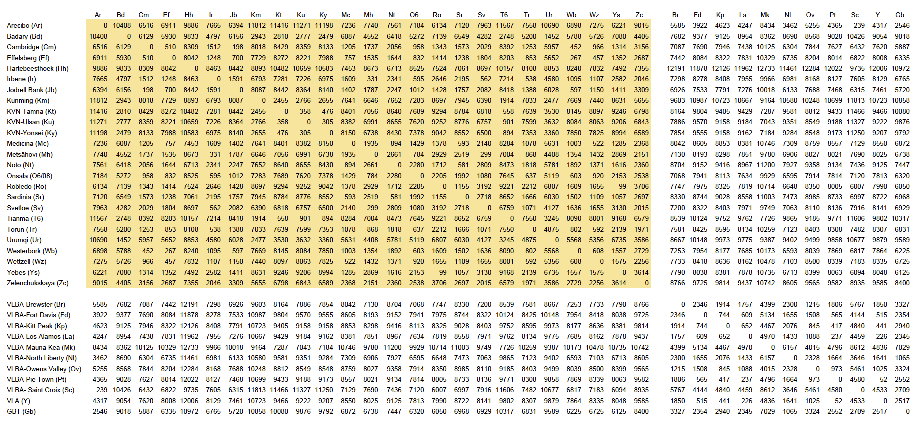
Baseline lengths (in km) between EVN stations (marked in yellow) and other global networks:
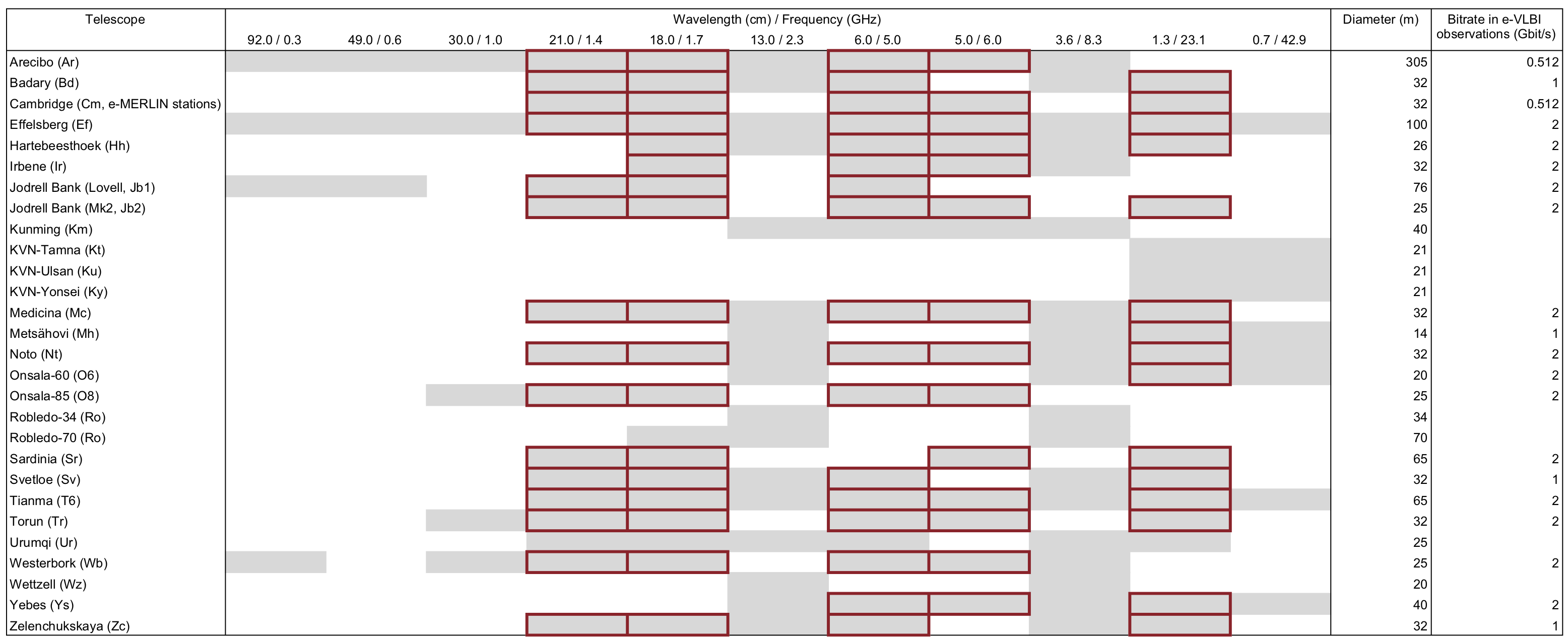
- Frequency coverage and real-time (e-EVN) capabilities
- The available frequencies at the EVN stations are shown in the table below (disk observations (grey) and real-time EVN observations (e-VLBI - red). The dish diameter for each station and the maximum bitrate at each station available for e-VLBI projects is listed in the last two columns.
- Sensitivity, (u,v) coverage and source visibility
-
The EVN achieves microJansky sensitivity on typical observations (several hours long). The observing declination limit for the EVN is -30 degrees, while sources are circumpolar for most EVN telescopes for declinations > 50 degrees.
The EVN Observation Planner can be used to determine when a target can be observed and the theoretical rms thermal noise for a given observation based on the participating antennas, the observing band, bitrate, and the observing time and coordinates on the target source (if known). It also provides estimations of the field of view for a given time and frequency average, expected resolution, and (u,v) coverage.
The previous EVN Sensitivity Calculator can still be used for quick estimations.
(u,v) coverage
The (u,v) coverage indicates the resultant quality of the eventual radio image obtained during observations. To learn more about UV coverage go here. These are examples of the typical (u,v) coverage achieved in EVN observations. You can use the EVN Observation Planner to determine which coverage would result from your planned observations.
Examples: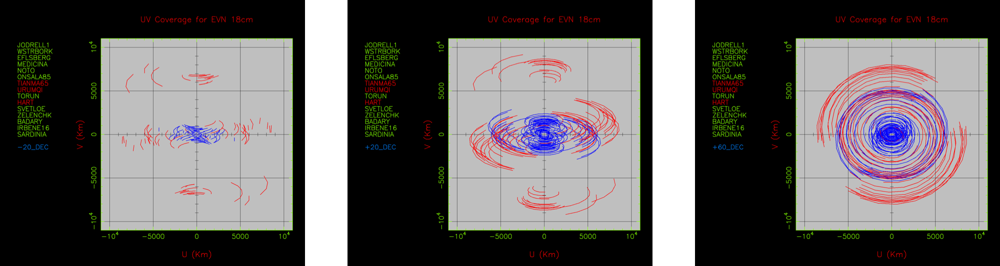
From left to right the images demonstrate UV coverage at -20 degrees, 20 degrees and 60 degrees declination.
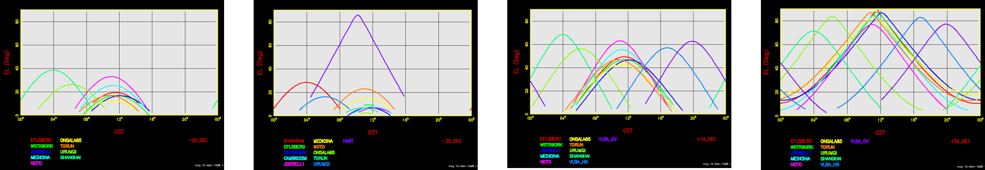
Source visibility
The EVN consist of a network of antennas spread over the Earth. The majority can be found in Europe, with additional stations in Asia, Africa and North America. This implies that not all antennas will likely be able to observe the source during the full observation, depending on the source coordinates and the duration of the observation.
In the following we show some examples of the source visibility for the different antennas for declinations of -30, -20, +10, and +50 degrees (from left to right, respectively). As before, you can use the EVN Observation Planner to determine the best times to observe your sources.
- Correlation of the data
-
Each individual antenna of the EVN records the obtained data locally, which are sent afterwards to JIVE in order to be correlated.
If the observation uses the real-time e-EVN mode (see operational modes in the following sections), then this transfer of the data is done in real-time, and thus the final data are available to the user within a few days after the observation. In case of the standard disk-recording mode, the data transfer and correlation happens within the following months after the observation.
By default, correlation occurs using the EVN software correlator (SFXC) at JIVE. The EVN software correlator allows pulsar gating/binning, more than 2048 spectral points across each subband/polarization, and multiple correlation phase-centers.
By arrangement with MPIfR correlator staff prior to proposal submission, limited time on the Bonn DiFX Correlator is also available.
Global VLBI projects can either be processed via JIVE's correlator or by the VLBA's correlator. A specific correlator may be requested for technical reasons, which must be explained in the proposal.
An EVN correlator-only proposal for the correlation of observations from non-EVN stations may also be submitted.
- Image limitations (field of view, resolving out large structures)
-
Imaging is affected by a number of limitations. The Field of View (FoV) and smallest/largest detectable angular structures are the principal limitations that arise from the array geometry, and these are outlined below.
Field of View
The undistorted Field of View (FoV) for the EVN is much smaller than the primary beam of the individual participating VLBI antennas. The two main effects responsible for this are bandwidth smearing and time smearing. Of these, time smearing usually places the most severe limitations on the FoV. For more information see the Field of View guide.
-
-
Observations over a finite frequency band.
-
Averaging visibilities over frequency range leads to radially smearing of sources located far from phase center in the image.
-
Peak flux is reduced but the total flux of the source is conserved.
-
Example table (10% reduction in response to a point source):
Channel BW B = 2.500 km
B = 10.000 km Comment 256 MHz 77.3 mas 19.3 mas Full spanned BW for 2 Gbps 32 MHz 0.619" 0.155" Single subband BW for 2 Gbps 0.5 MHz 39.6" 9.9" Typical continuum frequency-channel width
-
-
-
Stronger effect for longer baselines.
-
Depends on source position and baseline orientation.
-
Total flux density of a smeared component is not conserved.
-
Scales with increasing observing frequency.
-
Example table (10% reduction in response to a point source)
Integration time B = 2.500 km B = 10.000 km
2 s 22.2" 5.55" 0.25 s 178" 44.4"
-
More detailed tables summarising bandwidth and time smearing effects can be found in the FoV Guide.
Smallest/largest detectable angular structure
The angular size of the smallest structure that can usefully be discriminated is closely related to the synthesized VLBI beam. For a truly thermal-noise limited image, the minimum size would scale as ~synthesized beam size/Signal to Noise Ratio.
The angular size of the largest structure detectable by the EVN depends on the length of the shortest (projected) baseline. As an example, a conservative estimate of the largest detectable angular size for the Ef-Wb baseline of 266 km is about 0.1 arcsec at 18cm.
If the target has a radio structure on larger angular scales than given by the shortest projected baseline of the EVN, then joint EVN + e-MERLIN observations can be proposed.
-