
If the successful proposal is scheduled to be observed in the next session, the contact author of the proposal will receive an informative email about how to prepare the observations. This email will require the contact author to submit a key file to JIVE at least 2 weeks prior to the observation. If help in the schedule preparation is needed, please contact the EVN User Support at JIVE.
SCHED/pySCHED software
The EVN schedule (.key) file can be compiled by using the pySCHED software. pySCHED is a Python wrapper of SCHED developed by JIVE. Installation details can be found on the GitHub repository of pySCHED (please follow the recommendations and if errors occur, write to pysched@jive.eu). If installed correctly, the prepared .key file can be run with pySCHED as
sched.py [-p] -k {keyfile}
to generate various scheduling files (the optional parameter -pretrieves the graphical mode in order to be able to make plots about the observation). As long as pySCHED is connected to the internet, it will retrieve the latest frequency setup for your experiment. Please use the following template as reference to prepare the schedule.
Making a key file
The following steps will explain the parameters in the different sections of the template file that need to be adjusted for your project (highlighted as {PARAMETER}).
1. Cover Information
expcode  = '{EXPERIMENT_CODE}'
version  = 1
expt     = '{EXPERIMENT CODE}'
piname   = '{PI NAME}'
address1 = '{PI INSTITUTE NAME}'
address2 = '{PI INSTITUTE STREET}'
address3 = '{PI INSTITUTE CITY}'
address4 = '{PI INSTITUTE COUNTRY}'
email    = '{PI EMAIL}'
phone    = '{PI PHONE}'
obsphone = '{PI PHONE}'
Here please enter the relevant information concerning the experiment to be observed (assigned experiment code), and contact details of the contact author/Principal Investigator.
2. Correlator Information
obstype  = 'VLBI'
correl   = 'JIVE'
corpol   = 'on'
coravg   = {TIME AVG IN SECONDS}
corchan  = {NUMBER OF CHANNELS PER SUBBAND}
cornant  = {NUMBER ANTENNAS}
corwtfn  = 'uniform'
corsrcs  = 'standard'
cortape  = 'ftp'
These are the parameters to be used during correlation. Please update the number of antennas that are scheduled for your experiment (CORNANT), and the number of channels per subband (CORCHAN) and the time averaging (CORAVG). Note that JIVE will confirm the final correlation parameters with the PI before correlation.
3. Program Control
overwrit
sumitem = el1, early
If overwrit is specified, SCHED will overwrite any output files that already exist on disk. By default, SCHED will abort if it finds any old files of the same names as those it is trying to create.
In this section you can modify the output information that is written in the .sum file (after running SCHED/PySCHED) per antenna and per observing scan. Often used attributes for SUMITEM are:
el1 (el2): Quotes the elevation of each antenna, in degrees, at the beginning (end) of the scan.early: Seconds before the antenna is on source. Negative values mean that the antenna is not on source by the time the scan starts.az1 (az2): Quotes the azimuth of each antenna, in degrees, at the beginning (end) of the scan.slew: Seconds that each antenna requires to move from the previous source to the current source in the scan.dwell: Total duration of the scan (in second) once the antenna is on source.
For the full list of SUMITEM, see here.
4. Source Catalog
srccat /
    equinox='J2000'
    source='{SOURCE NAME}' ra={hh:mm:ss.ssss} dec={dd:mm:ss.sss} vel={VELOCITY} vref={REFERENCE FRAME} vdef={VELOCITY DEFINITION} /
endcat /
List here all sources that you want to observe and are not available in the standard SCHED (calibrator) catalogs. Include the name, coordinates, and, only in case of spectral line experiments, please add the velocity information of the source (vel=, vref=, vdef=):
- vel: velocity of the source, in km/s, within the vref reference frame.
- vref: reference frame for vel (L = Local Standard of Rest, H = heliocentric, G = geocentric).
- vdef: velocity definition (R = radio definition, O = optical definition).
5. Frequency Setup
{SETINI FILE CONTENT}

setup = {SETINI SETUP NAME}  ! For example:  setup = evn6cm-2Gbps-32MHz.set
Please add the general frequency setup for the observation. You will receive this information from JIVE prior to the observation. The setup written here refers to the setups that are stored in ~/.pysched/setup/.
Note that if you use a non-standard setup or you are using the NRAO SCHED program instead of pySCHED, you will need to put explicitly here the full information concerning your setup.
6. Start of Observation
YEAR = {YEAR} MONTH = {MONTH} DAY = {DAY} START = {START TIME HH:MM:SS} optmode = scansopminel = 9 stations = {LIST OF STATIONS TO BE INCLUDED}
Specify when the observation starts (year, month number, day, and time of the day in UTC format), and the scheduled stations. All this information is available from the EVN Block Schedule.
- Antenna names and codes
- The antennas that are scheduled for your observation would be quoted in the EVN Block Schedule (you may receive a dedicated email if you are the PI of the scheduled observations). pySCHED does not use the full name of the atennas. Instead, it uses either an abbreviated name of them or the two-letter code that you find in the EVN Block Schedule. In the following we list the correspondence between the full antenna names and the labellings to be used in pySCHED.
Antenna Name pySCHED name pySCHED two-letter code Cambridge cambg32m Cm Effelsberg eflsberg Ef Hartebeesthoek hart Hh Irbene irbene or irbene16 Ir or Ib Jodrell Bank (Lovell Telescope) jodrell1 Jb1 Jodrell Bank (Mark II) jodrell2 Jb2 Kunming kunming Km Medicina medicina Mc Metsahovi metsahov Mh Noto noto Nt Onsala onsala85 or onsala60 O8 or O6 Sardinia sardinia Sr Sheshan shanghai Sh KVN Tamna kvntn Kt KVN Ulsan kvnus Ku KVN Yonsei kvnys Ky Tianma tianma65 T6 Torun torun Tr Urumqi urumqi Ur Westerbork wstrbork Wb Wettzell wettzell Wz Yebes yebes40m Ys
7. The Scans
In this section, specify the list of scans to be observed. Commonly, a scan is defined as follows:source={SOURCE-NAME} gap={0:00} dur={2:00} /,
where dur is the total duration of the scan and gap the time gap between the end of the previous scan and the start of this one. Multiple scans can be compacted in a loop (group N rep X, where N defines the number of lines to be considered within the loop and X the number of times that the loop will be repeated).
In every observation we recommend to schedule at least two scans on fringe-finder sources (strong and compact calibrator sources). These scans will be used for the clock search at correlation time, and often for bandpass calibration (see Calibration section).
In the following we explain the basic examples of different types of observations that are provided in the template file:
Simple continuum observation
!!!!!!!!!!!!!!!!!!!!!!!!!!!!!!!!!!!!!!!!!!!!!!
! Simple continuum observation

source={FRINGE-FINDER} gap=0:00 dur={5:00} /

source={TARGET} gap={3:00} dur={3:00} /
group 1 rep {X}
	source={TARGET} gap={0:30} dur={14:30} /

source={FRINGE-FINDER} gap={3:00} dur={5:00} /
In case the target source is strong enough on all baselines (implying that there are unresolved or barely resolved strong source components), the calibration can be performed directly on the target, and it can be observed in subsequent scans. As explained in the System Temperature Measurements section, gaps of at least 10 seconds with antennas on source must be scheduled every 10-13 minutes to provide accurate system temperature measurements.
NOTE that with this approach, no astrometric information can be recovered from the target.
Phase-referenced continuum observation
!!!!!!!!!!!!!!!!!!!!!!!!!!!!!!!!!!!!!!!!!!!!!!
! Phase-referenced continuum observation

source={FRINGE-FINDER} gap=0:00 dur={5:00} /

source={PHASE-CALIBRATOR} gap={3:00} dur={2:00} /
group 4 rep {X}
	source={TARGET} gap={0:00} dur={3:00} /
	source={PHASE-CALIBRATOR} gap={0:00} dur={2:00} /
	source={TARGET} gap={0:00} dur={3:00} /
	source={PHASE-CALIBRATOR} gap={0:30} dur={1:30} /

source={FRINGE-FINDER} gap={3:00} dur={5:00} /
When the target source is too faint (less than ~100 mJy on any baseline), it cannot be used to conduct the main calibration of the data. Then, one needs to rely on a nearby strong and unresolved source (phase calibrator; see Calibration section). The phase calibrator must be observed alternately with the target to interpolate the solutions from the calibrator to the target.
Phase-referenced spectral-line observation
!!!!!!!!!!!!!!!!!!!!!!!!!!!!!!!!!!!!!!!!!!!!!!
! Phase-referenced  spectral-line observation

source={FRINGE-FINDER} gap={0:00} dur={5:00} dopsrc={TARGET NAME} /

source={PHASE-CALIBRATOR} gap={3:00} dur={2:00} dopsrc={TARGET NAME} /
group 4 rep {X}
	source={TARGET} gap={0:00} dur={3:00} dopsrc={TARGET NAME} /
	source={PHASE-CALIBRATOR} gap={0:00} dur={2:00} dopsrc={TARGET NAME} /
	source={TARGET} gap={0:00} dur={3:00} dopsrc={TARGET NAME} /
	source={PHASE-CALIBRATOR} gap={0:30} dur={1:30} dopsrc={TARGET NAME} /

source={FRINGE-FINDER} gap={3:00} dur={5:00} dopsrc={TARGET NAME} /
For this kind of observations a Doppler correction source must be specified with dopsrc in each scan. For target and phase calibrator this must be the same source (typically the target) to apply the same velocity correction to these sources.
Polarization observation
!!!!!!!!!!!!!!!!!!!!!!!!!!!!!!!!!!!!!!!!!!!!!!
! Polarization observation

source={FRINGE-FINDER} gap=0:00 dur={5:00} /

! EVPA
! Every 1 hour
source={POLARIZATION-CALIBRATOR} gap={0:00} dur={5:00} /

source={PHASE-CALIBRATOR} gap={3:00} dur={2:00} /
group 4 rep {X}
	source={TARGET} gap={0:00} dur={3:30} /
	source={PHASE-CALIBRATOR} gap={0:00} dur={2:00} /
	source={TARGET} gap={0:00} dur={3:30} /
	source={PHASE-CALIBRATOR} gap={0:30} dur={2:00} /

source={POLARIZATION-CALIBRATOR} gap={0:00} dur={5:00} /

source={FRINGE-FINDER} gap={3:00} dur={5:00} /
To properly calibrate the polarization D-terms, a polarization calibrator must be scheduled periodically along the observation (likely every hour; see Calibration section).
- More on polarization observations
-
There are two aspects to proper calibration of polarisation-sensitive VLBI observations: (1) D-term calibration, the calibration and removal of the instrumental polarisations, or D-terms, for each antenna and (2) position angle calibration, the calibration of the absolute orientation of the polarisation position angles (PPAs).
D-term calibration
The D-terms can be determined from either (1) an unpolarised source or (2) a source with a simple polarisation structure.
(1) If a strong unpolarised source is chosen, a single observation scan of 8-10 minutes on that source is sufficient.
(2) In the case of a polarised source, it is necessary to observe it over a wide range of parallactic angles (exceeding about 90 degrees). Usually, scheduling five or six scans with a duration of several minutes is sufficient.In some cases, one of the other calibrators scheduled in the observation may be suitable as a polarisation calibrator, as long as the source is known to have a simple polarisation structure or is unpolarised. Some good polarisation calibrators at frequencies up to 15 GHz are 3C84 (resolved source with a complex structure but the emission is unpolarised), OQ208 (slightly resolved source but of unpolarised emission), and DA193 (very compact source with weakly polarised emission).
Position angle calibration
The lack of sources with constant polarisation position angles (PPAs) on VLBI scales makes impossible to determine the PPAs with VLBI standalone observations. Thus it is necessary to obtain simultaneous or contemporaneous polarisation measurements with a connected interferometer of the same compact polarization calibrator. By comparing the orientation of the PPAs for the total VLBI-scale polarisation with their known orientation in the connected interferometer observations, it is possible to determine the necessary rotation to calibrate the VLBI polarisation angles. To achieve this, the EVN observations should contain five or six scans on the polarisation calibrator with durations of several minutes spread over the full observation. Instead of conducting dedicated simultaneous or contemporaneous observations with connected interferometers, it is sometimes possible to retrieve the same PPA information from public databases as the University of Michigan Radio Astronomy Observatory database, the VLA/VLBA Polarisation Calibration Page, and the Master EVLA POLCAL Database. However, in this case, there is no guarantee that observations of the selected PPA calibrator sources are conducted close in time to the EVN observations. It is important to try to have the measurements from connected interferometers as close in time as possible to the EVN observations, since the polarisation of compact sources can vary on timescales of days or weeks.
Note that it may be possible to use observations of a compact source with a simple polarisation structure for both D-term calibration and PPA calibration, allowing to spend less total time on the polarisation calibration. Here, it is necessary to find a source that is both relatively highly polarised and has a simple polarisation structure.
8. Output SUM file
SCHED/PySCHED produce different output files. You may want to look at the .sum file to verify the schedule of your observation.
The example below shows the scan summary section included in the output of the created .sum file for a given experiment using sumitem = el1, early.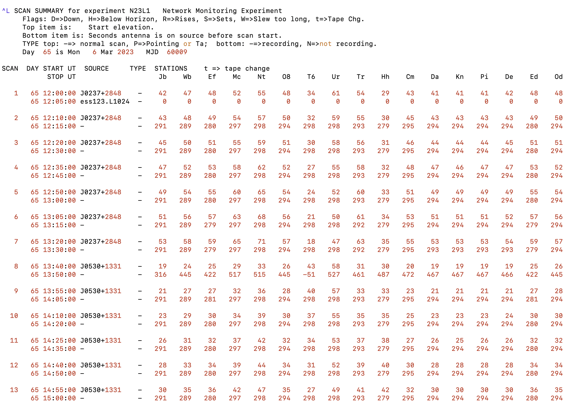
This is a summary of all scans that will be observed in the observation, with the relevant data (indicated in the sumitem command) for each station (columns). In this example, the first row of each scan shows the elevation of the source at the start of the scan. The second row quotes the number of seconds that a station is on source before the start of the scan. Negative values show for how long the antenna is still moving from the previous source position until it reaches the current one.
For System Temperature measurements, the values from the second row should be at least 10 seconds every 10-13 min for all antennas with non-coninuous Tsys measurements (see System Temperature Measurements section).
Things to consider
- dwell parameter
-
The
dwellparameter is an alternative way to specify the duration of a scan. The difference toduris that the start time of the scan is delayed until all antennas are on-source (taking into account the slewing and settle time of each antenna). This implies that telescopes will be idle waiting for the slowest antenna to reach the source position instead of recording once they individually reach the source. For EVN observations this must not be used since the different telescopes of the EVN have significantly different slewing times, and thus a significant loss of on-source time can be encountered. In addition, due to the flexibility of the EVN (specially in the e-EVN mode) some antennas may be added in the last minute, producing that the full schedule would change ifdwellis in use. Therefore, please always use the parameterdurinstead. - System Temperature Measurements
- The EVN telescopes regularly measure system temperatures using noise diodes. Some telescopes can measure the temperatures continuously. However, the other stations measure them only when there are long enough time gaps between observing scans. This refers to time gaps that guarantee at least 11 seconds on source for these stations at the beginning of the scan. One of these long gaps must be scheduled every ~10-13 minutes (SCHED/PySCHED will provide warnings for intervals between gaps of more than 15 minutes). You can check the length of time gaps by looking at the .sum output file (see Output section) using the early attribute in sumitem (see Program Control section).
- Effelsberg Pointing
- Effelsberg is a 100-m antenna that requires periodic pointing scans. To achieve a good pointing precision, Effelsberg has to have an eight-minute period without recording every four hours (for 6, 5, and 3.6 cm; i.e. C, M, and X band), and every two hours (for 1.3 and 0.7 cm; i.e. K and Q band). No pointing scans are required for 21 cm (L band) or longer wavelengths. This eight-minute period can be achieved by either having a gap of eight minutes in the schedule or taking Effelsberg out of the station list for some scans.
- Jodrell Bank (Lovell Telescope) and Tianma slewing limitations
- The Lovell Telescope (typically known as Jodrell1, or Jb1, in EVN schedules) and Tianma (T6, since April 2026) have a slewing limitation of 12 source-changes per hour (which is equivalent to a ten-minute cycle time between two sources). If you want to go to a faster cycle time and/or are using a traditional phase-referencing cycle like the one quoted above, it is required to schedule an observing pattern that omits the Lovell Telescope every other reference-source scan.
A convenient way to perform this is illustrated in the following phase-referencing example:
In this way, the Lovell Telescope (Jodrell1) will not observe every other scan on the phase calibrator. Instead it will keep observing the target source.group 4 rep {X} stations = jodrell1, all other antennas source={TARGET} gap={0:00} dur={3:00} / source={PHASE-CALIBRATOR} gap={0:00} dur={2:00} / source={TARGET} gap={0:00} dur={3:00} / stations = all other antennas ! NOTE THE LACK OF jodrell1 source={PHASE-CALIBRATOR} gap={0:30} dur={1:30} / stations = jodrell1, all other antennas ! Continue with the full array
Required calibrator sources
A regular VLBI observation requires to observe different calibrator sources in order to properly calibrate the data. Depending on the science and observational case, multiple strategies and sources may be desired. In a general case, we require to observe:
- At least two scans during the observation on a very bright and compact source (fringe-finder). These data will be used to clock search the full observation (synchronize the data from all antennas in time), and they can be used during the data reduction to perform the bandpass correction and the single-band delay calibration (see our EVN Data Reduction Guide and EVN Tutorials for further information). This source does not require to be near your target source (although nearer would imply less slewing time for the antennas when moving from one source to another). But all antennas must be observing some of the fringe-finder scans.
- Phase-referencing calibrator source. Unless the target is very bright, compact, and no absolute astrometry information is required from the data, the target source must be observed following a phase-referencing strategy (see sections above). A nearby calibrator source needs to be observed regularly in order to properly calibrate the data and transfer these solutions to the target source data. You can see our section on calibrator selection to pick a good calibrator source.
- If polarization information is required from the observation, a polarization calibrator is required to be observed. See the section above on polarization observations for further details.
- If the e-MERLIN antennas are observing, we recommend to observe at least one scan on 3C286, the amplitude calibrator for this array. This source will help you to better calibrate the amplitudes (gains) of each of these antennas by following their usual calibration approach with a model of the source. This can be used during EVN observations by applying this strategy to only the e-MERLIN antennas.
To-Do list for schedule checking
The following list can be used as last step before sending your schedule file to the EVN to verify that all information is correct. It goes through the main points that could go unawarely wrong. In any case, note that the EVN User Support will also verify your schedule before observations.
- Verify that the experiment code in EXPCODE is the correct one (including epoch letter if needed; e.g. EA123A).
- The date and UT range (start and end time) must match the allocated block schedule.
- Set a lower-limit elevation for antennas (right after the start date/time of the observations at the beginning of the scan section):
optmode=scansopminel=7 or 9 - Targets sources
- Targets approved by the PC for the particular epoch.
- Verify that the coordinates are the correct ones for the target.
- Frequency setup. Check that the loaded setup is the correct one.
- Check that the scheduled stations are the ones in the block schedule.
Note differences between On60/On85, Ir/Ib, or Jb1/Jb2 antennas. - Gaps in the scheduled scans (Tsys measurements, and pointing).
- Antennas without continuous system-temperature (Tsys) calibration require to have a 'gap' at least every 10–15 min for Tsys measurements. The most up-to-date table with the continuous calibrations at stations is in the MPI Wiki. Although this information can also be seen in the .sum output file (see section above).
- Effelsberg requires a 8-min gap for pointing every four hours at C band (5 GHz) and above, and every two hours at K and Q band (20 and 40 GHz, respectively).
- Always use gaps larger than 11s to avoid problems encountered earlier with how field-system interprets minimum gap-length at some stations.
- All stations should always be observing at least two scans on fringe-finders during the observation. If the observation is long (e.g. >5 h) then more fringe-finder scans is desirable.
- Sources and Scans:
- Certify that the phase-referencing calibrator (if any) is bright and compact enough.
- The phase-referencing calibrator must be close to the target source.
- All sources are far from the Sun (check the .sum file).
- For spectral line experiments.
- Make sure that targets and their calibrators (phase-referencing, bandpass, etc.) use the same DOPSRC source.
- If possible, check the VEL/VDEF/VREF parameters that control the Doppler calculation, especially with narrow subband-BW.
- For polarization experiments, suitable calibrators (D-term and EVPA) should be observed.
- For eMERLIN antennas, if they are included, schedule an amplitude calibrator (3C286) for them.